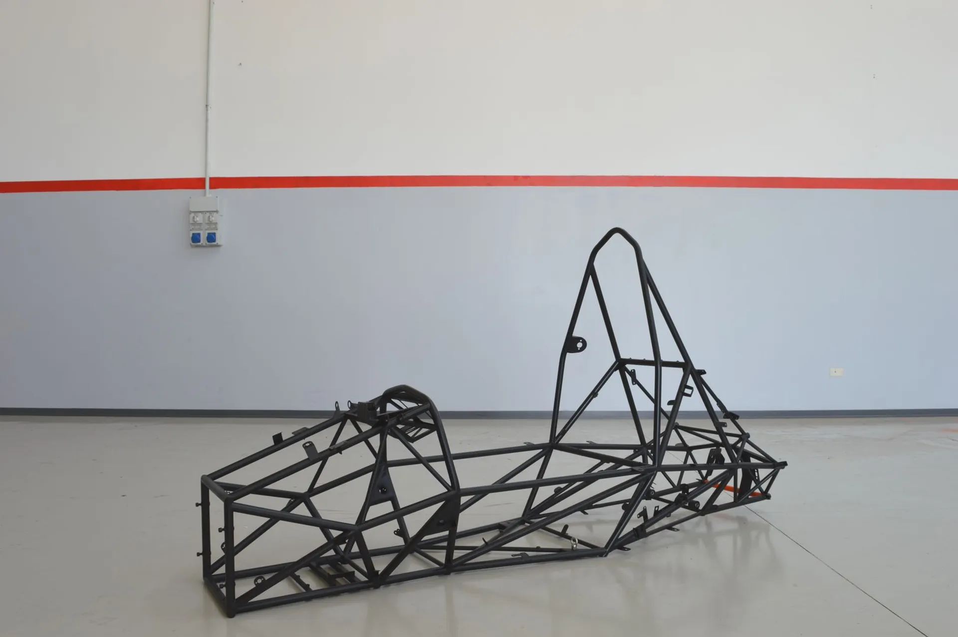
FR-15T chassis
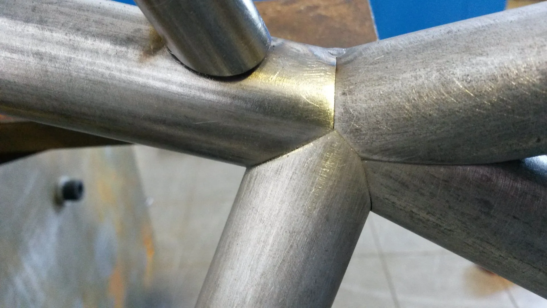
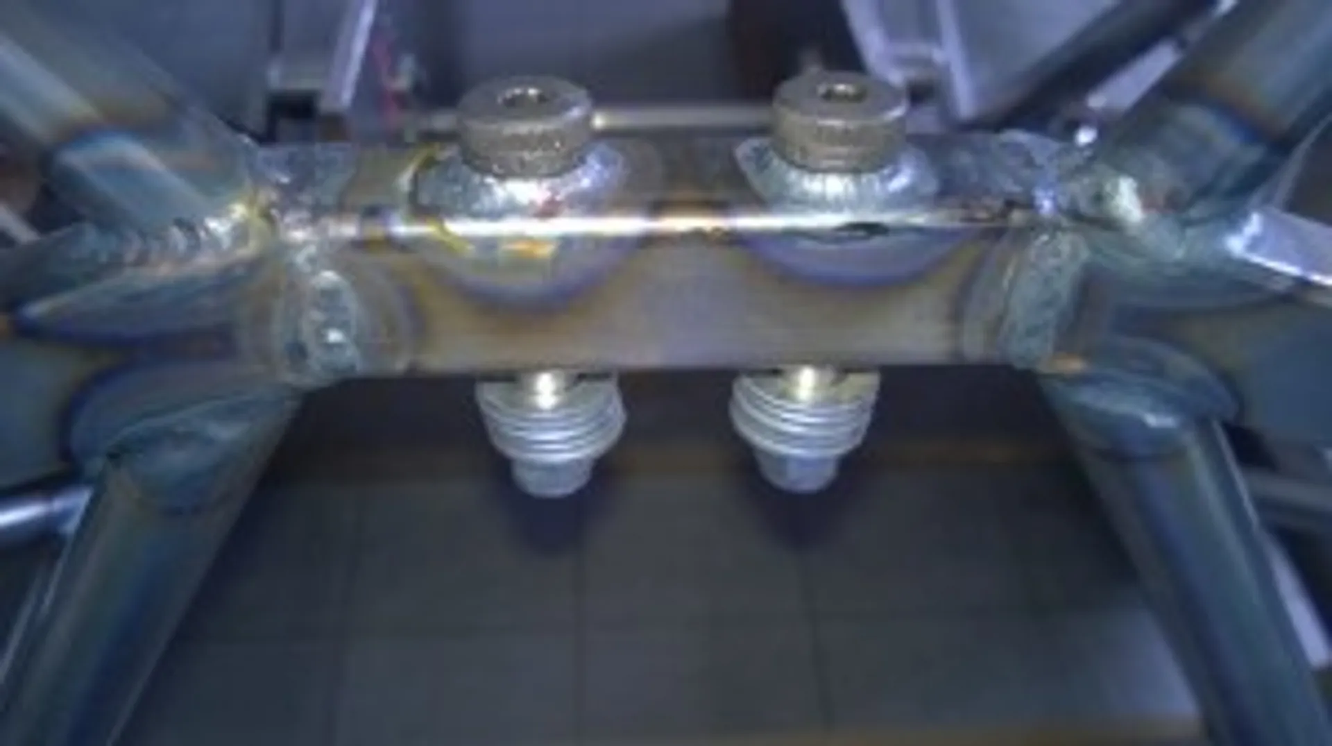
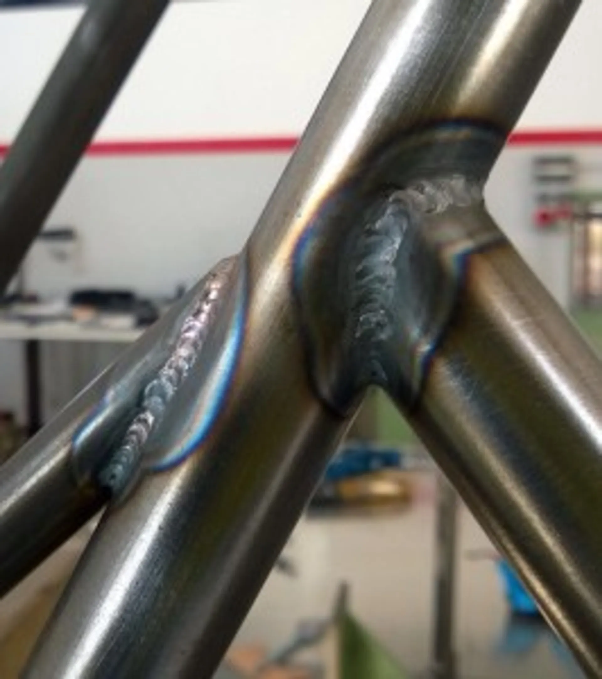
The frame of the FR-15T is a truss made of AISI 4130 (25 CrMo4) steel tubes cut by 2D laser cutting, bent by CNC bending and then welded by TIG welding. The latter guarantees excellent joint quality. The whole was assembled using appropriate welding jigs and a striker bench in order to achieve a high degree of precision in terms of the positioning of the suspension connections.
The design objectives were to ensure optimum ergonomics for the driver, a high local stiffness of the suspension attachment points, so as not to introduce sagging that would alter the behaviour of the car given by the suspension kinematics, and finally to have a high torsional stiffness.
The chassis design consisted of three main phases: the definition of the geometry, the preparation of the three-dimensional model and the FEM analysis phase.
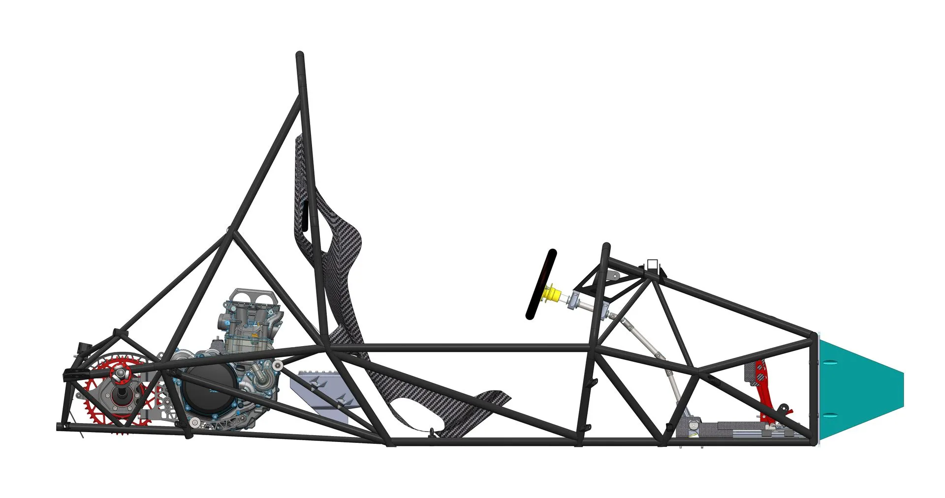
In the first phase, a bench was set up to measure the space required for the driver, the best driving position and the positioning of the various controls such as steering, pedals and gearbox. With regard to the choice of rider position, the opinions of all the team members were taken into account and the most suitable position was then chosen. After that we started with the realisation of a wireframe of the chassis, trying to make the suspension attachment points coincide with well-trimmed points, precisely to make these points very rigid and not to introduce sagging. Once the layout of the car was also defined in terms of the installation of the components on the chassis, the basic geometry was then completed. This last step was done by trying to keep the centre of gravity of the system as low as possible and balancing the inertia tensor of the car.
The next step was to create the actual three-dimensional model, in which all the tubes were drawn so that they could be cut with a 2D laser cutter. During this phase, some modifications were made to the geometry, paying close attention to the various components installed, and trying to create profiles on which it was possible to create weld seams in the least number of passes.Lastly, the welding jigs were designed, made by water cutting and subsequent machining from solid.
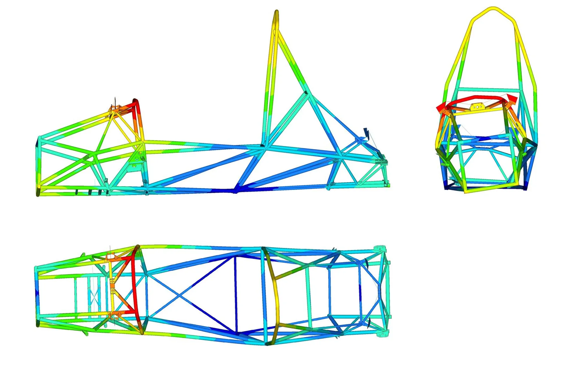
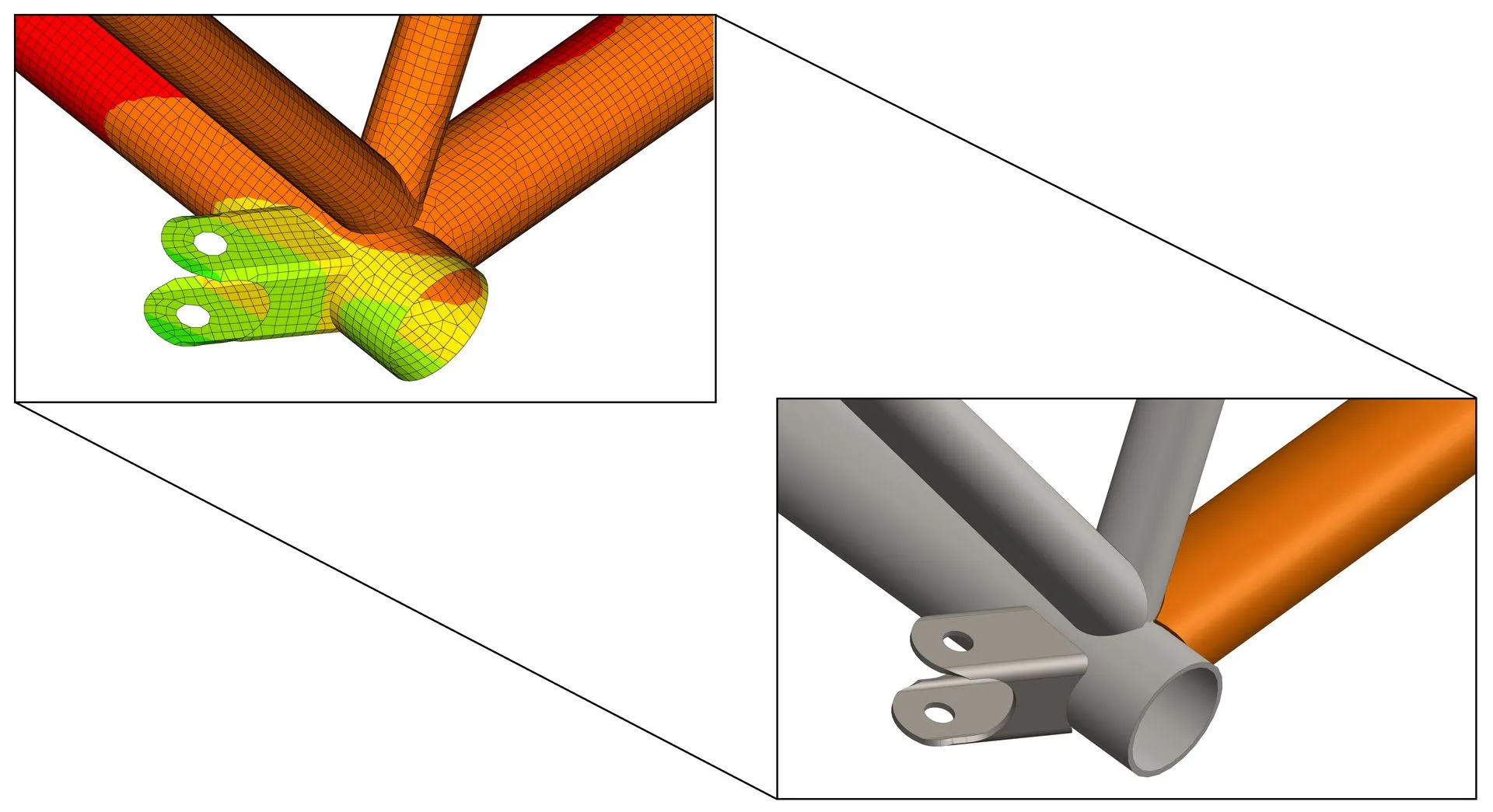
The last phase was the analysis one. In this phase, the local stiffness of the various suspension attachment points was evaluated by means of a two-dimensional FEM model using shell elements. In these simulations, it was possible to characterise the stiffness of the various points considering only static conditions. Although these conditions do not represent the actual working conditions, these analyses made it possible to assess which points were the weakest in order to reinforce them with gussets, which can also be used for the design of future frames as a comparison value.
Finally, the torsional stiffness of the frame and in particular its structural efficiency was evaluated. To assess this, one-dimensional FEM analyses were carried out by means of a free-free analysis with which the first torsional eigenfrequency of the system was derived. Knowing then the inertia tensor of the frame, the torsional stiffness was derived. Through this simulation it was also possible to assess the decoupling between the chassis resonance frequency and the rolling frequency of the car.