Electronically-controlled differential
WHY LOCK THE DIFFERENTIAL?
The locking of the differential is necessary to establish an adequate traction value following a reduction in grip on a drive wheel in non-straight driving conditions; in fact, momentarily preventing the two axle shafts from being independent of each other will reduce tyre slip in critical conditions to a few moments. The lockable differential can be controlled mechanically as in the case of the LSD type; this results in a constant locking percentage under all conditions of use and a worsening of the vehicle’s handling due to its intervention characteristic. To compensate for these limitations, we have decided to use an electronically controlled semi-active differential. Thanks to this type of control, it is possible to vary the locking percentage realised instant by instant, guaranteeing a distribution of the value of torque transmitted on each axle shaft and a maximisation of the vehicle’s traction in any driving condition, thus increasing handling.
E-DIFF FRT OPERATION
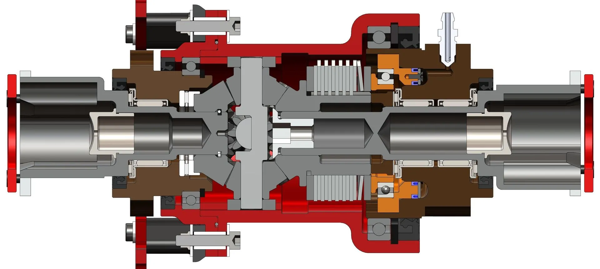
As far as the operation of the system we have designed is concerned, we can start by analysing the control logic with which the need and extent of locking is established. By means of specific sensors, the angular speed of the wheels and yaw rate of the vehicle are acquired; these data are then sent to and processed by the ECU, which detects the incipient wheel slip on the inside trajectory. The actuator subunit receives the input from the ECU and, via the actuator, pressurises the oil that allows the piston inside the differential to move. The actuator allows the generation of the thrust required to lock the differential by exploiting the friction between the contact surfaces of the clutch plates.
DESIGN AND DEVELOPMENT
The design and development work behind what was achieved was divided into the following macro areas:
- differential;
- drive;
- control logic;
- control unit.
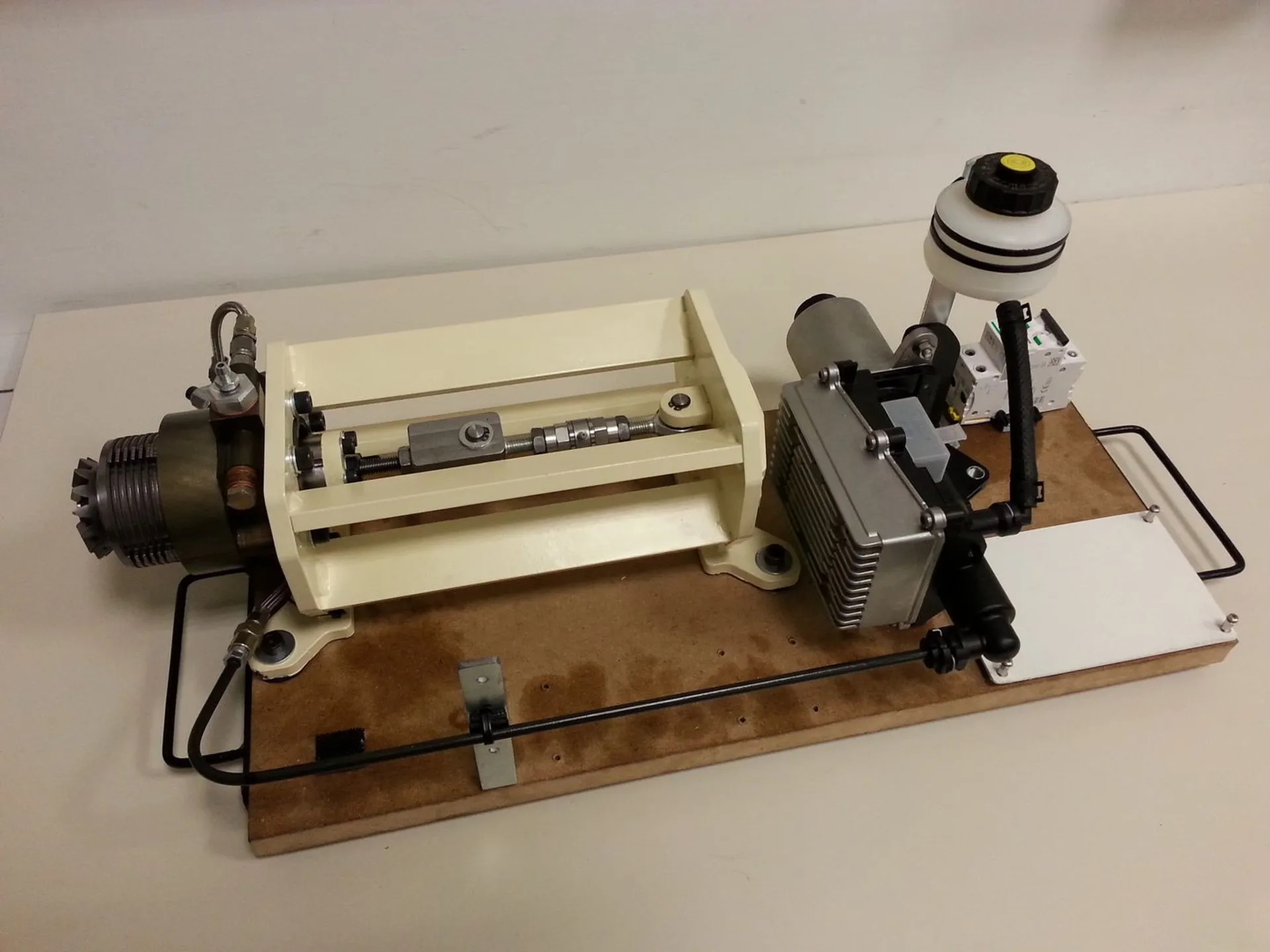
We started with a preliminary study on how to realise the differential body construct and the part inherent to the electro-hydraulic drive, taking the maximum system pressure and drive time as constraints. On the basis of this, the initial foundations of the layouts of these two constructs were laid; at the same time, the control logic required to operate the system was implemented. In order to further investigate the studies obtained from the simulations, it was decided to design and build a test bench for testing the control unit-drive-actuator assembly, validating and implementing the results of the previous simulations.
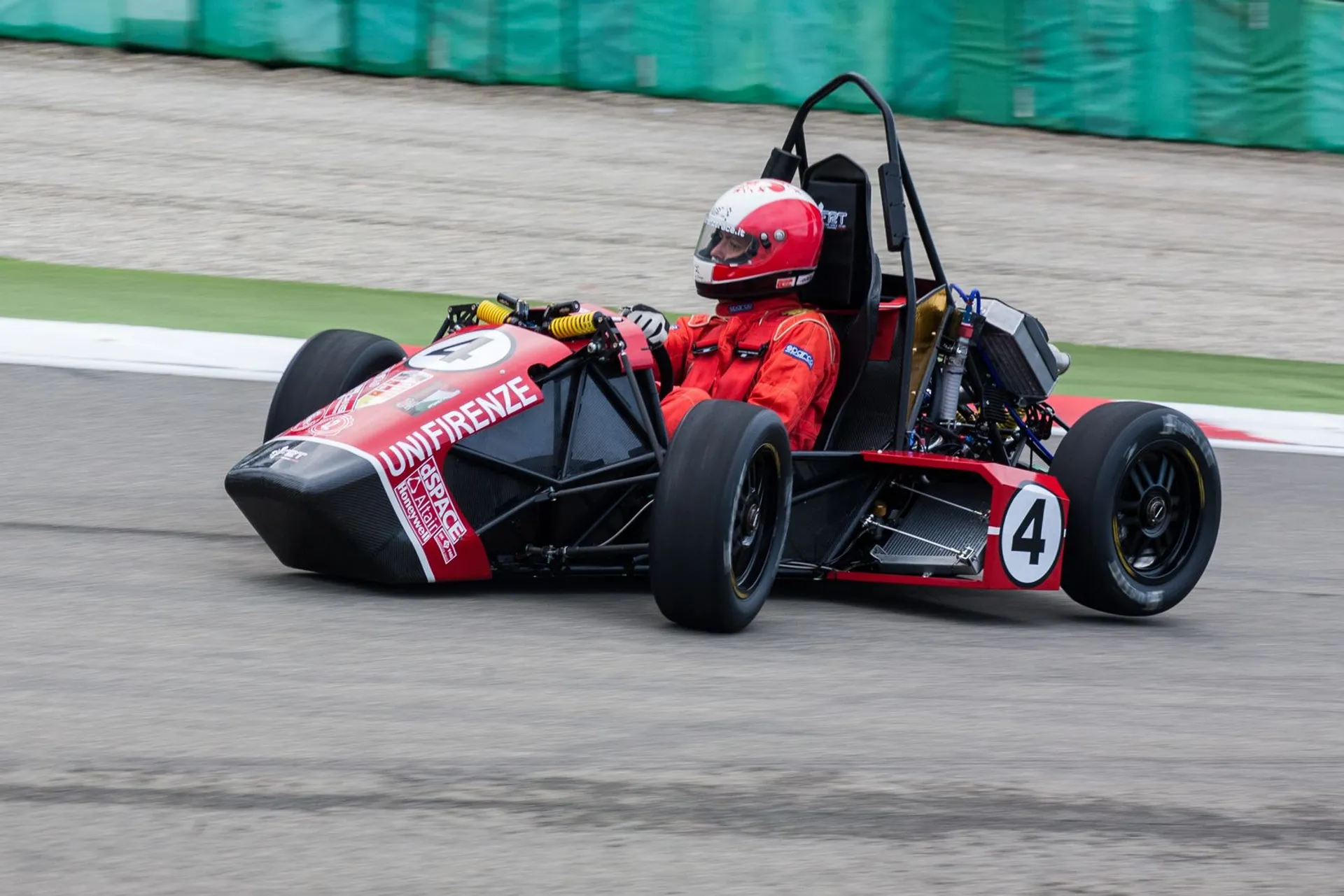
Once a good amount of data had been obtained, we then moved on to the realisation of the final version of the entire system so that it could be tested in real operating conditions directly on the FR-15T car, the first version of which is shown in Fig.2. Following what emerged from the races and tests, it was then decided to work on the first version of the system, defining the second release according to the following objectives for the 2016 season
- increased reliability and stiffness of the assembly;
- reduction of assembly and mounting time inside the car;
- mass reduction.
The main new features introduced with this second version are the separation of the internal housing for the clutch-gearbox, made of steel, and the external casing needed to secure the differential inside the car, made of 7075-T6. The system connecting the differential to the chassis has also undergone some modifications, saving weight. The fruit of the development work carried out over the winter will therefore be used to tackle the current FSAE season.
We would like to thank: in particular BACCI Trasmissioni Meccaniche; Meccanica 42; dSPACE; VI-GRADE; RGB; GIEFFE Racing Parts.